 |
 |
 |
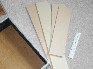
A quick trip
to a model shop procured some Basswood. Its light, quite strong and can be cut
readily with a sharp craft knife. Its also relatively soft so that it would
protect anything that knocks into it. I bought a selection of thicknesses and
some super strong PVA wood glue.
A note
on glues here. I used a glue called Tite Bond which is very strong but takes a
while to set but its waterproof. You could work with something like a simple
Aliphatic wood glue favored by modelers which sets a bit
faster. |
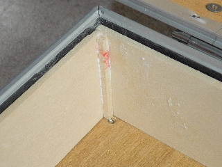
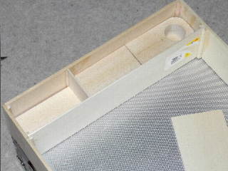
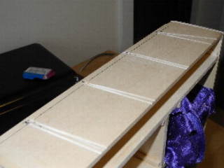
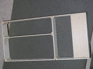
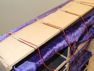
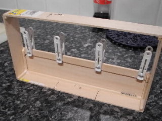
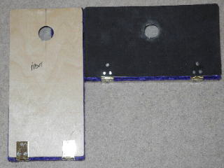
Heres the inner skin of the case being assembled. The
thicker pieces of Basswood were cut to size and fitted into the case and glued
together with basic joints plus a gusset of pre-formed square Basswood for
strength. This is the basic structure of all joint in the case as work
progressed. The inner skin of the case was left free so that it could be
removed from the case if needed later on. |
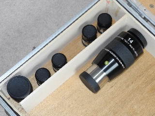
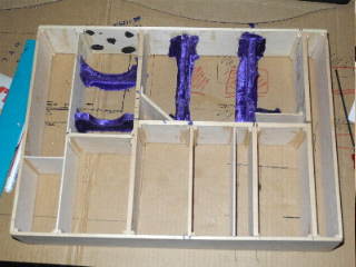
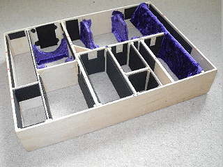
At the outset I made up various
templates to get the best possible density of equipment into the case. As the
project evolved I made some changes as I went along. Heres a picture of the
inner skin of the case with its first divider installed (as per the original
plan). As this divider would run from side to side it was made of thicker
Basswood, like the inner skin to give the interior some strength.
Some eyepieces have been put in to
gauge the space and check there is enough finger room to get stuff in and out
of the case. |
 |
 |
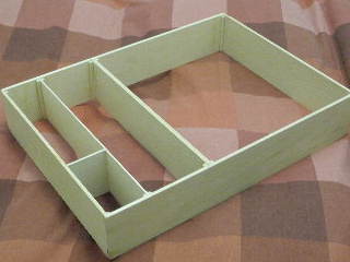 |
| Heres the inner skin removed
from the case. Each cross member is supported by a gusset of the square cut
Basswood. |
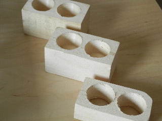
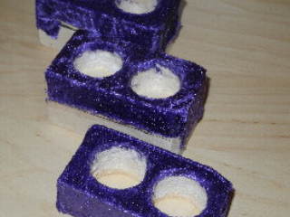
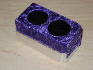
Heres the first divider with some Balsa blocks
installed. These would have holes cut into them to hold the smaller 1.25"
eyepieces. Each of the blocks was designed to be removable so that alternate
blocks could be fitted for different eyepieces (or omitted altogether). Another
cross members of thinner Basswood divides the two groups of blocks. |
Heres the inner skin with another thick cross member
fitted. The original design called for all wood partitions that run entirely
across the case to be of a larger gauge to keep the inner skin
rigid.
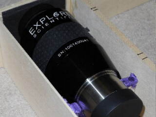
The second cross member has a
space for two larger eyepieces. The very hefty Explore Scientific pair of 14mm
100' and 30mm 82' |
 |
 |
 |
| A small deviation from
plan......Originally the case was designed to be a bit more general purpose and
not built towards a specific set of EPs. However some of the EPs would always
be retained. I decided to make a small cradle to hold one of the heaviest of
these (the two Explore Scientific eyepieces). The 14mm is slightly thinner and
no usable space could be created down the side of the eyepieces so I decided to
create some space underneath it by elevating it away from the bottom of the
case. |
Heres some thin panels of Basswood laminated together
and cut to the diameter of the explore Scientific 14mm 100' EP. The cut out has
a band of soft child safe rubber (i.e. no fumes or toxins) which I bought from
a craft shop. The rubber is bonded on using a conventional PVA based fabric
glue. |
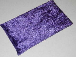
After the rubber strip had bonded down it was covered
with the material I had chosen for the inside of the case. This is a deep
bluish purple synthetic felt. Before use it had been washed in a washing
machine for two or three washes to remove any lint and run over with a lint
removing roller. The material was quite cheap but as it turned out I needed a
lot more than I had thought. |
 |
 |
 |
| Next the front and back of the
cradle rings were covered in felt. These were cut out against a paper template
and glued onto the wood. There is surplus at the ends of the cradle as this
will be folded underneath the material at the join line later and hide any
gaps. |
To give the larger eyepieces, which would be put into
the case laying flat, some protection at their ends some squares of rubber were
added. These have a very slight interference fit with the eyepiece stop to stop
in moving about in transit. |
Heres both of the cradles installed for the Explore
Scientific 14mm EP. This was taken at an earlier test fitting showing one
cradle half felted while the other has only the rubber 'mattress' applied. Part
of the secret of building this type of project is a relentless testing of each
fitting and a constant, almost obsessive, retesting of each idea to see if it
can be done better. |
 |
 |
 |
| And, once the glue had fully
dried, heres the ES 14mm inserted. Unfortunately the space created underneath
it wasn't large enough to be of much use. Its mostly used to keep a silica gel
bag under the EP to reduce any moisture in the case. |
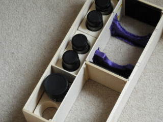
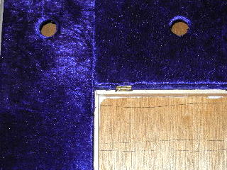
These are the modules for the 1.25 eyepieces drilled out
using a large wood drill. They were drilled to different depths to accommodate
differing 1.25" barrels. If I were building again I would drill them out to a
uniform depth. Lining the bases of these proved to be quite a
challenge. |
Here are the 1.25" EP modules inserted into the case
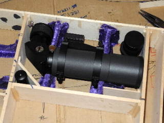
carcass with some 1.25" EPs in place to assess spacing. |
 |
 |
 |
| A picture of the 1.25" holders
with their velvet applied. Getting the felt to fit well inside the holes proved
to be a hard challenge...... |
In the end I settled for using some off cuts of
Protostar flocking paper. This also had problems and tended to come loose. It
was eventually sealed down with a thin bead of Superglue around the edge where
it joins the velvet material |
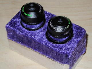
And finally a pair of UO orthoscopics nestled into the
1.25" holders for a test fitting. Needless to say no EPs were put in for
testing until the glues had dried fully. |
 |
 |
 |
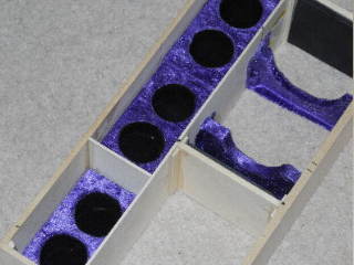
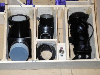
Heres a progress picture showing
the various elements completed so far. The cradle for the 2" EP and the 1.25"
holders.
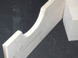
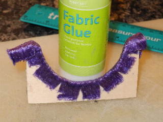
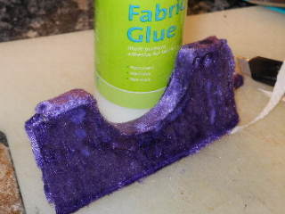
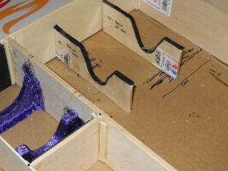
One of the bigger challenges for the case was how to carry two
possible finders. A Stellarvue F50 RACI 8x50 and a TAL 6x30mm.
This was quite a taxing problem the SV F50 is a lot
larger. The Stellarvue made it impossible to find a good fit because its quite
bulky in height. |
It eventually dawned on me that the F50 can have its EP
removed shortening its height which opened up some new possibilities. You'll
see how this works later in the build. The finders would ride on a pair of
cradles. These have quite complex curves as can be seen above to accommodate
both finder sizes. The smaller curve at the base of the cradle is to hold the
TAL 6x30 while the larger opening at the top of the cradle allows the wider
bodies F50 finder to be held safely and securely. |
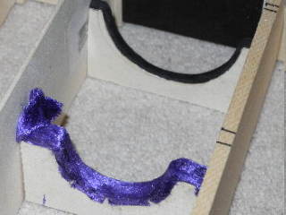
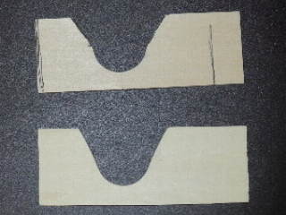
Heres a test fitting of the cradles. A lot of thought
and testing went into the final arrangement. The carcass of the case in this
picture is sat on some cardboard with various markings for me to work out how
to fit all the bits together. You'll see also the cradles have writing as
reminders about which way various parts fit. |
 |
 |
 |
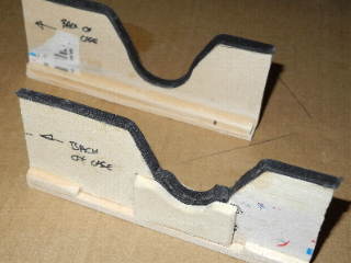
| Here are the two almost
completed cradles. The near one has a built up area at the base of the curve to
support for the TAL 6x30 eyepiece. Both of the cradles have a base applied to
give them some extra rigidity and help with test fittings. |
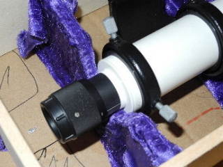
Heres the Stellarvue F50 RACI finder in place for a test
fitting. The SV50 has a removable eyepiece like a normal telescope with a
helical focuser. Once it dawned on me to have the F50 carried in pieces the
design came together quite fast. You can see how the F50 rides towards the top
of the cradle. |
And heres the TAL 6x30 installed for a test fitting. You
can see how the thicker base in the cradle gives the eyepieces stalk a good
wide support. You can see how the TAL finder snuggles down to the vase of the
cradle.
The pen marks on the cardboard
underneath are for sizing the extra parts. |
 |
 |
 |
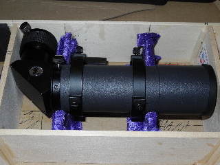
| Heres the finder area of the
case. The F50 finder is installed with its eyepiece (top right) and its Rigel
Pulse Guide illuminator (bottom left). The additional compartment at the bottom
right is for a filter. |
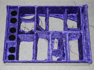
The picture above shows the wooden carcass of the case
approaching completion. Most of the compartments have been installed and only a
few small sub dividers remain to be sized and fitted. By this point in the case
design I had been back for more Basswood at least three times and the cost of
the case was rising rather quickly. |
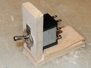
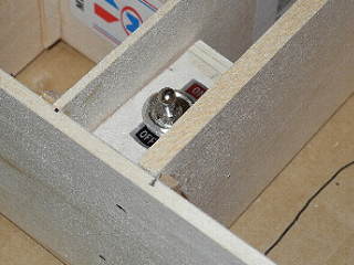
My plan had been from the outset to have something a
little different and part of this was an illumination system for the case. Here
is the first part of the lighting. A switch ! I shopped around for something
retro looking as I did want the case to be a little bit yesteryear in look and
feel. |
 |
 |
 |
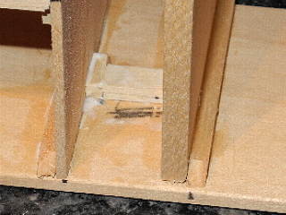
| This is the location for the
switch. It now has a built up ledge which will hold one side of the
switch. |
And finally the switch in place for a test fitting to
make sure all is is well. |
The compartments around the switch were designed to hold
a 2" diagonal , 1.25" diagonal and a Baader Skysurfer V OR to be used as
general compartments for other equipment/eyepieces in the future. |
 |
 |
 |
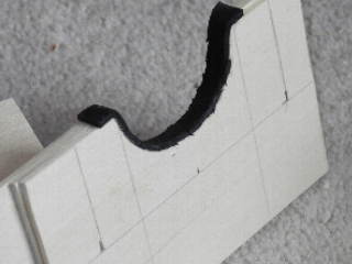
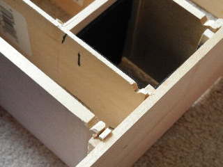
| As part of the illumination
system these holes grooves were cut into the side of the cases carcass. The
holes will hold a 12v LED and the grooves are to allow the LEDs wires to
fit. |
A small diversion........It was a few weeks before I
could shop for LEDs and wire so I made a start on the lid of the case. The
first part was to create a space for the Synscan handset and small controllers
to fit. |
Heres one of the lid modules almost completed. The large
slot will hold the Synscan hand control and the smaller slot will hold a fan
controller and dew controller. The 'pouch' will hold cables and
leads. |
 |
 |
 |
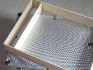
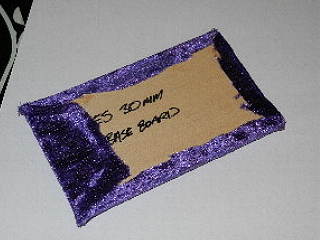
| Meanwhile on the main case some
extra wood was bought. One of the joys of this project was there was always
something to do - like take a drive for more supplies. The new supply of wood
was for 'base boards' these would form the base of the case and give some of
the bigger equipment a soft bedding. This one is for the ES 30mm eyepiece
showing its backing. |
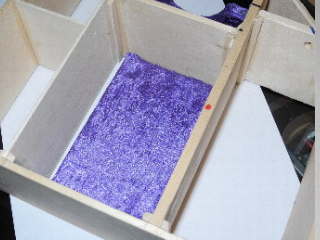
Here is the 30mm EP base board. Once again the velvet
like material was glued down with a waterproof fabric PVA glue. |
And finally a base board in place for another test
fitting. In fact this one was later thrown away as it turned out to raise the
30mm EP slightly too high. Another of the joys of this project was spending
time making things only to scrap them afterwards !!!!!! |
 |
 |
 |
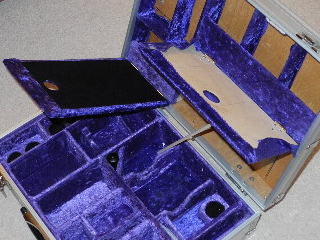
| But despite many set-backs the
case is finally starting to take shape. Heres a progress report picture showing
all of the wooden compartments installed, some of the rubber inserts and even
some of the velvet installed. |
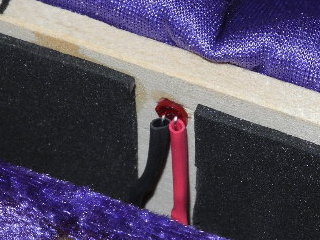
In order to get cables through the case for the LEDs,
small notches were cut along the cable path for the cables to run
in. |
Heres an LED installed. Working out the sequence for
getting these in with the velvet was problematic and it was quite definitely a
'think before you act' job. The velvet had small holes made in it at LED
locations by applying a hot soldering iron to it until it burnt through as a
perfect hole. Then the LED was glued into place wires soldered to it before
being covered with heat shrink tubing. |
 |
 |
 |
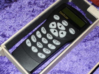
| Back to the case lid - heres the
Synscan handset in place. Its held down by a friction fit of rubber around it
and, eventually, will have a Velcros back. |
Back to the wiring. the LEDs are wired with short tails
of thin wire. The thin wires will eventually be soldered to a kind of buswire
that will run around the case. |
And heres another progress report picture with much work
having been done. The thin slot alongside the right of the case holds
filters. |
 |
 |
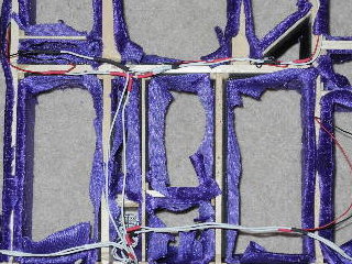 |
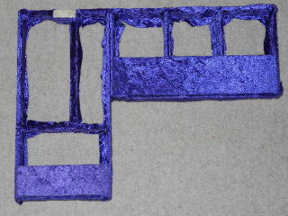
| Finally the case has all of its
velvet and LEDs installed. Applying the velvet was hard work. The left to right
panels were cut as a single panel with slits to fit around the verticals. The
vertical panels in this picture were then covered. Each piece was slightly
oversized to cover gaps and the finally sealed with a small bead of superglue
along joins. |
You can just make out two LEDs in this picture along the
edge of the case near the 1.25" eyepieces. |
Here is the back of the carcass with the white buswires
in place. They link to the switch at the bottom of the picture. Power comes
into the case via a small 2.1mm DC jack that's drilled through from the outside
of the case allowing it to be powered from my powertank. I was reluctant to
have batteries in the same case as eyepieces in case of leakages. |
 |
 |
 |
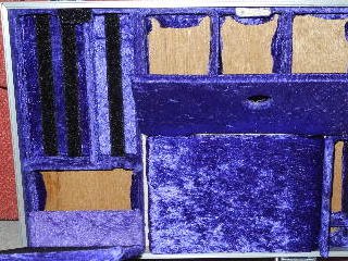
| Another progress picture. The
carcass has now been fitted into the case and some of the base boards have been
fitted. In the end I used rubber sheeting covered with velvet. Each baseboard
was slightly oversized to give a good snug fit and hide any small
gaps. |
Finally the base of the case is completed. To allow any
fumes from the glues to vent the case was left open with no equipment in it for
a week. The inner frame/carcass is not glued in. Its quite a tight fit and I
wanted it removable should the need arise. This turned out to be smart as
within a few months I did need to make some modifications |
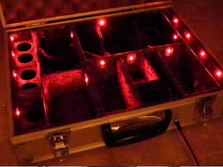
Heres how the LEDs looked when lit up. Needless to say
these were tested prior to installing the lower carcass. |
 |
 |
 |
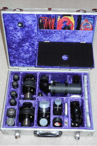
| And heres a picture of the
finished lower half of the case. |
Continuing with the lid a second module was assembled.
This one is to hold small leads and accessories. The pegs are holding on a
small lip to the rear of the compartment to made the edge a bit more
rigid. |
And here are the two lid compartments completed with
their covering. The bare space at the top of the left hand one is where a
Velcro tab will be fitted later to hold the covers for these
modules. |
 |
 |
 |
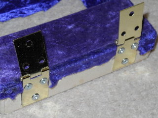
| A range of different hinges were
tried to hold the covers to the lid modules. None were perfect or what I had in
mind. |
The lids for the two modules were made from Baltic ply
NOT basswood. The lids needed to be a bit more rigid, more hard-wearing. The
right hand lid has been covered with rubber sheet in this picture and both have
had finger holes drilled so they can be opened. |
Heres how the lid of the case was starting to look. The
inner lids have a backing of Protostar flocking which made for a neater trim
than I could manage with the velvet for this part of the project. |
 |
 |
 |
| The lid modules are held in
place by a pair of Basswood strips glued to the lid of the case. Each module
has shims between it and the edge of the case glued into place so that they are
held by glue on all four sides to give them strength. |
The controller holders to the right
in this picture have Velcro strips applied. The backing of the case is
alternate strips of rubber covered with velvet and thin strips of ply covered
with Velcro. This approach was needed to stop the Velcro ripping the velvet
away from its rubber backing. |
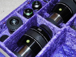
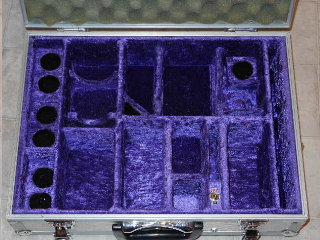
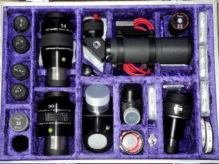
Heres a picture of the inside of the case after a few
weeks use. Spare cables can be stored underneath the finder and you can also
see large silica gel bags underneath the ES 14mm EP and the finder. The biggest
change though has been the disposal of the Baader Skysurfer V and the
acquisition of a new EP in the lower right. |
| |
|
|
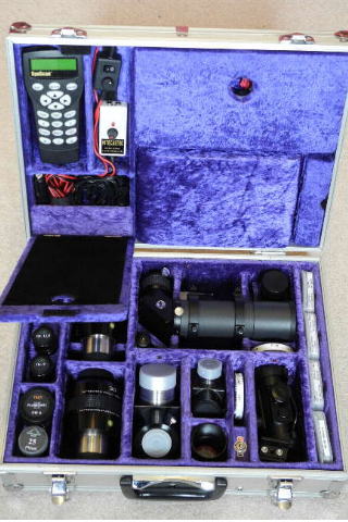 |
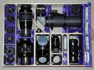
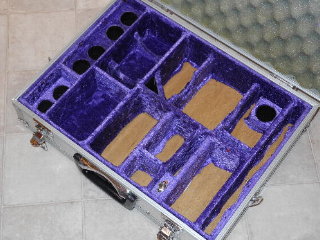
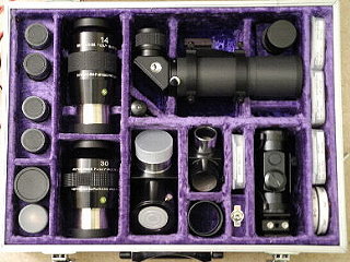
Finally.....two pictures of the completed case as it was
originally built. The upper left module holds controllers and their leads while
the upper right module contains leads, cleaning kits and small tools for
collimation. You can see in the final pictures the Velcro tabs that hold the
upper modules lids shut.
A late addition to the design was the small compartment
in the lid to the bottom right which holds spare batteries and
fuses.
The large central area of the lid was originally to have been a
compartment for extra filters but in the final build there was not enough space
available to justify increasing the cost of the project even further and the
space was used solely as a large foam pillow covered with velvet to act as a
pad for the finders.
The final cost
of the case was probably in excess of £200 and quite possibly more but I
found it worthwhile. The project had its ups and downs and there were days when
I wished I had never started it but the final results justified it. Its a
beautiful case that's completely unique in a world of mass market consumerism.
It also holds more equipment than the two cases I had originally
!
This was not to be the final chapter though
so read on..... |
 |


